Cómo instalar una toma de aire frío en un Chevy Silverado sin códigos MAF
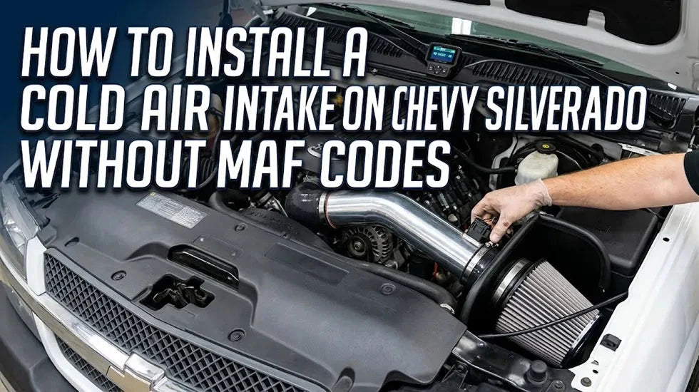
Instalar una toma de aire frío en un Chevy Silverado no es un trabajo difícil. En una camioneta GMT800 en buen estado, un principiante cuidadoso puede terminarlo en unos 45 a 90 minutos con herramientas manuales básicas. El problema comienza cuando alguien se apresura a transferir el MAF, aprieta el tubo antes de alinear el escudo térmico o deja un acoplador de silicona apenas colgando del borde del tubo.
Así es como un simple proyecto de sábado se convierte en un ralentí inestable, una luz de "revisar motor" y tres horas mirando el compartimiento del motor preguntándose qué salió mal.
Esta guía se centra en el Chevy Silverado 1999-2006 y las camionetas GMT800 relacionadas equipadas con los motores Vortec V8 de 4.8L, 5.3L o 6.0L. El mismo flujo de trabajo básico se aplica a muchos kits de admisión Duramax de Silverado 2500HD y 3500HD, pero el enrutamiento de los tubos, la ubicación del filtro, la carcasa del MAF y los herrajes de montaje son diferentes. Revise su motor antes de aflojar la primera abrazadera.
- Tiempo de instalación típico: Aproximadamente 45-90 minutos para un kit completo atornillable, asumiendo que los herrajes de fábrica no están atascados o dañados.
- Pasos principales: Retire el tubo de admisión y la caja de aire de fábrica, transfiera el MAF en la dirección correcta, monte el escudo térmico, alinee el tubo y los acopladores, apriete las abrazaderas e inspeccione la camioneta después del arranque.
- Error más común: Un sensor MAF al revés, un conector MAF suelto o una fuga de aire después del MAF.
- Requisito de ajuste: Muchos kits específicos para vehículos conservan la geometría MAF compatible y están destinados a la calibración de fábrica, pero esto debe confirmarse para el kit exacto.
- Cuándo detenerse: No conduzca la camioneta si se detiene, acelera bruscamente, entra en modo de potencia reducida o establece inmediatamente un código relacionado con el MAF.
Antes de comenzar: Confirme la camioneta, el motor y el kit de admisión
Escúcheme en esto: no compre ni instale solo por el desplazamiento. Una Silverado 5.3L 2002 y una Silverado 5.3L 2014 pueden llevar la misma insignia, pero su enrutamiento de admisión, controles del motor, disposición del MAF y puntos de montaje no son los mismos.
El mismo problema aparece en las camionetas diésel. Los LB7 2001-2004 y LLY 2004.5-2005 son ambos motores Duramax de 6.6L, sin embargo, sus sistemas de admisión no son intercambiables. Verifique el año, el código del motor, el modelo y el ajuste del producto antes de desarmar el sistema de fábrica.

Confirme la generación y el motor de la Silverado
Este tutorial se centra en aplicaciones GMT800 con motor Vortec, incluidas muchas camionetas Silverado 1500 de 1999 a 2006 con los siguientes motores:
- Vortec de 4.8L: Comúnmente el LR4 en camionetas GMT800 de servicio ligero.
- Vortec de 5.3L: Comúnmente el LM7, L59 o motor de camioneta Gen III relacionado.
- Vortec de 6.0L: Comúnmente el LQ4 o LQ9, según el vehículo.
Algunas camionetas "Classic" de 2007 conservan la carrocería GMT800 más antigua y la disposición de admisión, mientras que las camionetas de carrocería nueva de 2007 utilizan una disposición diferente. Nunca asuma que "2007" cuenta toda la historia.
Para una visión más amplia de las diferencias entre modelos de servicio ligero y pesado, lea nuestra guía sobre las diferencias entre Silverado 1500, 2500 y 3500. Esa distinción importa porque una toma de aire de diésel 2500HD no es simplemente una versión más grande de una toma de aire de gasolina Silverado 1500.
Disponga cada pieza antes de quitar la caja de aire
Abra la caja y coloque cada componente en un banco limpio. Haga esto antes de que la camioneta de fábrica se convierta en una pila de abrazaderas sueltas y piezas de plástico.
Un kit completo de admisión estilo escudo térmico puede incluir:
- Tubo de admisión
- Filtro cónico de alto flujo
- Escudo térmico o carcasa del filtro
- Acoplador de silicona recto
- Acoplador reductor
- Acoplador de joroba, según el diseño
- Abrazaderas de tornillo sin fin o de perno en T
- Adaptador MAF o herrajes de montaje MAF
- Soportes de apoyo
- Ribete de goma
- Tornillos, arandelas, tuercas y aisladores de vibración
Los acopladores de aspecto diferente suelen ser diferentes por una razón. Un reductor destinado al lado del cuerpo del acelerador puede deslizarse sobre el adaptador del filtro, pero eso no lo hace correcto. Compare los diámetros internos y use el diagrama de instalación suministrado con el kit.
Reúna las herramientas y prepare el área de trabajo
Normalmente no necesita un elevador. Sí necesita suficiente luz para ver la parte inferior de la caja de aire, el bloqueo del conector MAF y cualquier clip de manguera que se esconda detrás del tubo de admisión.
- Juego de llaves de vaso métricas y carraca
- Extensión corta
- Destornillador de tuercas o destornillador de punta plana
- Destornillador Phillips, si lo requiere el kit
- Alicates
- Herramienta de extracción de molduras o clips
- Linterna
- Toalla de microfibra limpia
- Pequeña bandeja magnética para herrajes
- Escáner OBD-II para la comprobación del primer arranque
Trabaje en un motor frío y estacione en un terreno nivelado. Si las instrucciones del kit requieren la desconexión de la batería, retire primero el terminal negativo. En una camioneta más antigua, asegúrese de saber si la desconexión de la corriente borrará los preajustes de la radio, la configuración del reloj o un código antirrobo.
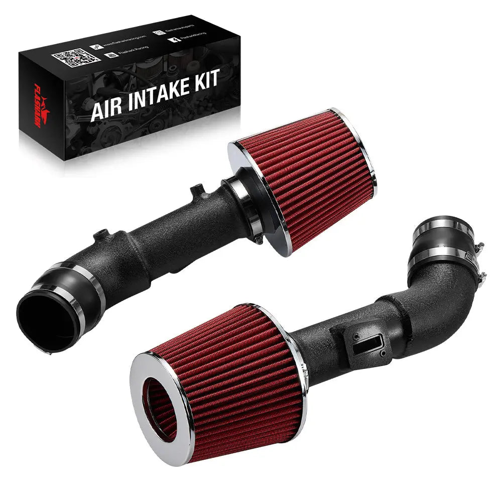
Para aplicaciones de gasolina GMT800 compatibles, la toma de aire frío del Chevy Silverado 1999-2006 utiliza un tubo de aluminio de 4 pulgadas, un filtro cónico seco y un escudo térmico. Verifique el modelo, el motor, la posición del MAF y la generación de la carrocería antes de realizar el pedido.
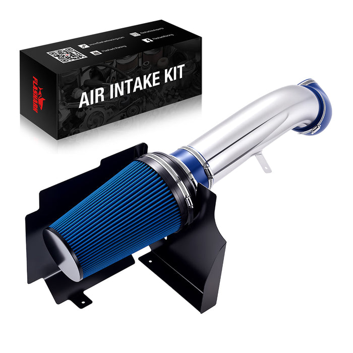
Aplicaciones compatibles con motores de gasolina V8 GMT800
Toma de aire frío Flashark Vortec de 4 pulgadas
Diseñada para camionetas y SUV Chevy y GMC 4.8L, 5.3L y 6.0L Vortec de 1999 a 2006 compatibles. Incluye un tubo pulido, filtro seco, escudo térmico, acopladores y herrajes de instalación.
$79.99 $129.99
Verifique el ajuste y el precio actualPrecio mostrado cuando se preparó esta guía. Las promociones y variantes pueden cambiar.
Paso 1: Retire la caja de aire y el tubo de admisión de fábrica de la Silverado
Tome una foto antes de tocar cualquier cosa. En serio. Fotografie la trayectoria de admisión completa, la flecha MAF o la orientación original, el enrutamiento de las mangueras, los clips de los cables y la forma en que la caja de aire de fábrica se asienta en sus soportes de goma. Diez segundos con un teléfono pueden ahorrar una hora más tarde.

Desconecte el arnés del MAF sin tirar de los cables
El conector MAF puede utilizar un bloqueo secundario. Deslice o levante ese bloqueo primero, luego presione la pestaña de liberación principal y tire del conector directamente lejos del sensor.
No intente meter un destornillador grande debajo del conector y girarlo. El plástico de veinte años se vuelve quebradizo. Una vez que la pestaña de bloqueo se rompe, el enchufe puede permanecer conectado en el camino de entrada, pero vibrar y soltarse en la carretera.
- Libere el bloqueo secundario.
- Presione la pestaña principal del conector.
- Tire del cuerpo del conector, no de los cables.
- Inspeccione los terminales en busca de corrosión, pasadores doblados o humedad.
- Coloque el arnés donde no pueda quedar atrapado debajo del nuevo tubo.
Afloje las abrazaderas y libere las mangueras conectadas
Afloje la abrazadera del lado del cuerpo del acelerador y la abrazadera cerca del MAF o de la caja de aire de fábrica. Por lo general, no es necesario quitar los tornillos de la abrazadera por completo.
Busque mangueras pequeñas, retenes de la línea de refrigerante y clips de cables unidos a la toma de aire de fábrica. Libérelos antes de levantar el tubo. Sacar la toma de aire con una línea todavía enganchada es una excelente manera de romper un accesorio de plástico que estaba perfectamente sano cinco minutos antes.
Retire la caja de aire de fábrica con cuidado
Dependiendo de la camioneta específica, la caja de aire inferior puede estar sujeta por pernos, pasadores de ubicación, ojales de goma o una combinación de ellos. Retire cualquier sujetador visible, luego tire de la caja hacia arriba con presión constante.
No deseche los ojales de goma ni los pernos de fábrica. El nuevo escudo térmico puede reutilizar uno o más puntos de montaje originales.

Guarde la caja de aire, el tubo, las abrazaderas y los herrajes originales juntos. Es posible que los necesite para solucionar problemas, inspección de emisiones, reventa, uso invernal o para devolver la camioneta a su estado original. Una admisión de fábrica completa es mucho más útil que una pila de piezas esparcidas por tres estantes.
Paso 2: Transfiera el sensor MAF en la dirección correcta
Esta es la parte que causa la mayoría de los dolores de cabeza después de la instalación. El sensor MAF mide el flujo de aire entrante para que la ECU pueda calcular el suministro de combustible. Es direccional, sensible a la turbulencia y se instala aguas abajo del filtro. Trátelo como un sensor, no como otro trozo de tubería.

Marque la dirección del flujo de aire antes de retirar el MAF
Antes de separar el MAF de la entrada original, identifique la flecha del flujo de aire en la carcasa. El aire debe viajar desde el lado del filtro hacia el cuerpo del acelerador y el motor.
Si la flecha es difícil de ver, use la posición original como referencia y coloque un pequeño trozo de cinta adhesiva en el lado que mira al motor. También anote la ubicación del conector eléctrico. Cuando se instala correctamente, el arnés de fábrica debe llegar al sensor de forma natural. No debe estirarse con fuerza como una cuerda de guitarra.
Manipule el sensor por su carcasa
No toque el elemento sensor. No lo limpie con un trapo de taller. No lo sople con aire comprimido, limpiador de frenos, limpiador de carburador o cualquier aerosol que esté en el banco.
Si el elemento realmente necesita limpieza, use un limpiador específicamente etiquetado para sensores MAF y déjelo secar completamente antes de la instalación.
Inspeccione el sello, el adaptador y los tornillos de montaje
Revise la junta tórica o la empaquetadura antes de instalar el sensor en su nueva posición. Un sello que falta, está doblado, cortado o pellizcado puede permitir la entrada de aire no medido al motor.
Apriete los pequeños tornillos del sensor de manera uniforme. Estos no son tornillos de culata. Un apriete excesivo puede romper una carcasa de plástico, deformar un adaptador o pelar una inserción roscada.
Caso práctico de taller: El arnés no debe ser una correa de sujeción
Recuerdo haber parado a la mitad de la instalación de un filtro de aire de GMT800 porque el tubo se veía bien, los acopladores se veían bien y cada perno había empezado a enroscar limpiamente, pero el arnés del MAF solo llegaría si lo estiraba con fuerza a través del tubo.
Esa fue la clave. La carcasa del MAF estaba girada en la dirección equivocada.
Lo giramos, reajustamos los acopladores y el conector encajó sin tensión. Esa corrección de cinco minutos fue importante. Dejarlo estirado habría cargado los cables cada vez que el motor se moviera sobre sus soportes. Si el arnés te está dificultando, detente y vuelve a verificar la orientación del MAF antes de apretar cualquier cosa.
Paso 3: Montar y ensamblar el escudo térmico
Un escudo térmico no es solo una pieza de metal negra añadida para que el kit parezca completo. Controla la posición del filtro, separa el filtro del calor radiante del motor y a menudo soporta el adaptador del filtro o el tubo de admisión.
Instale primero el embellecedor de borde y el adaptador de filtro
Por lo general, es más fácil instalar el embellecedor de goma, los soportes y el adaptador de filtro mientras el escudo está fuera del camión. Presione el embellecedor completamente en los bordes especificados para que no se suelte después de algunos ciclos de calor.
Mantenga las arandelas en el orden que se muestra en las instrucciones. Una arandela faltante puede permitir que un sujetador se salga de un soporte ranurado o que el escudo vibre contra la carrocería.
Comience a enroscar cada perno de montaje antes de apretar
Coloque el escudo térmico en el área de la caja de aire de fábrica y comience a enroscar todos los pernos a mano. Dé a cada sujetador varias vueltas limpias antes de aplicar una llave.
No apriete completamente el primer soporte mientras los otros orificios de montaje aún están a una pulgada de la alineación. Deje el conjunto lo suficientemente suelto como para moverlo hasta que el tubo de admisión y el filtro estén colocados.
Verifique la holgura del capó, el guardabarros, la manguera y el cableado
Inspeccione todo el perímetro del escudo. Asegúrese de que no esté aplastando una manguera de refrigerante, apoyándose en un telar de cableado o apoyándose en el guardabarros.
- El capó debe cerrar sin tocar el escudo o el filtro.
- El filtro no debe apoyarse contra un borde metálico afilado.
- El arnés del MAF no debe rozar contra el escudo.
- El tubo de admisión debe tener espacio para moverse ligeramente con el motor.
- El escudo no debe balancearse al presionarlo con la mano.
Baje el capó suavemente la primera vez. No lo cierre de golpe para "ver si despeja". Coloque una pequeña bola de plastilina o papel doblado sin apretar encima de un punto alto cuestionable, baje el capó con cuidado e inspeccione la compresión si necesita confirmar la holgura.
Paso 4: Colocar los acopladores de silicona, el tubo y las abrazaderas
Aquí es donde la paciencia rinde frutos. El orden correcto es simple: identifique los acopladores, coloque las abrazaderas primero, ensamble todo sin apretar, alinee todo el sistema y solo entonces apriete.

Identifique cada acoplador antes de la instalación
Un acoplador recto normalmente conecta dos diámetros similares. Un reductor une piezas con diferentes diámetros exteriores. Un acoplador de joroba añade flexibilidad y ayuda a absorber el movimiento del motor o pequeñas diferencias de alineación.
No elija un acoplador porque sea el primero que se pueda forzar en el tubo. Mida o compare ambos extremos.
Coloque las abrazaderas en los acopladores antes de unir las piezas
Deslice las abrazaderas sobre la silicona antes de empujar el acoplador en el tubo de admisión, el cuerpo del acelerador, la carcasa del MAF o el adaptador del filtro. Deje las abrazaderas lo suficientemente sueltas como para girar.
Apunte los tornillos de las abrazaderas hacia arriba o hacia un lado accesible del compartimento del motor. Debería poder alcanzarlos más tarde sin quitar el faro, la batería o la mitad del sistema de admisión.
- Mantenga el tornillo de la abrazadera alejado del capó.
- No permita que la carcasa del tornillo se clave en un telar de cables.
- No apunte la cola larga de la abrazadera a una manguera de refrigerante.
- Mantenga la banda de la abrazadera cuadrada con respecto al tubo.
- Colóquela detrás del reborde o labio elevado cuando el componente tenga uno.
Prueba de ajuste del sistema de admisión completo antes del apriete final
Conecte la admisión desde el cuerpo del acelerador hasta el filtro, pero deje todas las abrazaderas y soportes ligeramente sueltos. Gire el tubo hasta que el conector del MAF sea accesible y el tubo despeje las piezas circundantes.
Cada tubo debe extenderse lo suficiente dentro del acoplador para crear un sellado fiable. Un tubo insertado solo unos pocos milímetros puede salirse o gotear. Empujarlo demasiado puede distorsionar el acoplador, golpear el tubo contra otro componente o sacar el filtro de su posición.
Una vez que el sistema completo esté en su posición natural, apriete las abrazaderas gradualmente. No aplaste la silicona. La junta terminada debe resistir la rotación y el estiramiento a mano sin mostrar una ranura profunda, una protuberancia grave o un adaptador de plástico distorsionado.
Mucha gente aprieta la abrazadera del cuerpo del acelerador completamente, luego intenta forzar el extremo del filtro en su lugar. El tubo termina precargado contra el escudo térmico, el arnés del MAF se estira y un acoplador queda torcido. Mantenga el sistema suelto hasta que todos los componentes estén alineados.
Paso 5: Instale el filtro y vuelva a conectar todas las mangueras y sensores
En este punto, el camión puede parecer terminado. No está terminado hasta que pueda dar cuenta de cada enchufe, manguera, soporte, clip y abrazadera que haya tocado.
Asiente el filtro de aire completamente
Empuje el cuello del filtro completamente sobre su adaptador. Coloque la abrazadera sobre el área de sujeción sólida, no a la mitad del borde, y apriétela hasta que el filtro no pueda girar ni salirse a mano.
Confirme que el filtro no toque el protector térmico, el capó, la batería, el panel de la carrocería o el cableado cercano. Una pequeña holgura en reposo es importante porque el motor y la carrocería se mueven de forma independiente sobre baches y bajo el par.
Vuelva a conectar el MAF, el respiradero y los clips de retención
Vuelva a conectar el enchufe del MAF hasta que el pestillo principal haga clic, luego reinstale su seguro secundario. Tire suavemente del cuerpo del conector para confirmar que está seguro.
Vuelva a conectar cada manguera de PCV, respiradero o aire fresco incluida en la trayectoria de admisión de fábrica. Una conexión de respiradero olvidada puede convertirse en una gran fuga de aire no medido.
- Conector MAF bloqueado
- Manguera de PCV o respiradero conectada
- Retenedores de línea de refrigerante restaurados
- Clips de cableado asegurados lejos del tubo
- Sujetadores del escudo térmico apretados
- Abrazadera del filtro apretada
- Acoplador del cuerpo del acelerador apretado
- Acopladores del lado del MAF apretados
Realice una inspección práctica
No inspeccione solo con los ojos. Agarre el tubo e intente moverlo. Empuje suavemente cerca del filtro. Sienta cada abrazadera. Recorra cada junta desde el filtro hasta el cuerpo del acelerador.
Retire todas las herramientas, sujetadores sueltos, embalajes y trapos del compartimiento del motor. Cuente sus herramientas si es necesario. Un dado dejado cerca de la cubierta del ventilador puede arruinarle el día rápidamente.
Primera puesta en marcha: qué comprobar antes de conducir
Vuelva a conectar el terminal negativo de la batería si lo quitó. Siéntese en el asiento del conductor, apague la radio y el ventilador del climatizador, y encienda el camión sin acelerarlo inmediatamente.
Deje el motor al ralentí y escuche
Un sonido de admisión ligeramente más notable es normal. Un silbido fuerte y agudo al ralentí no es algo que deba descartarse automáticamente.
Escuche por:
- Ruido de inducción constante: A menudo normal con un filtro cónico abierto.
- Silbido agudo: Posible acoplador, junta del MAF, PCV o fuga en el respiradero.
- Cascabel metálico: Tubo, tornillo de la abrazadera o protector térmico tocando otra parte.
- Aumento repetido: Posible orientación del MAF, conector, fuga de aire o problema de señal de flujo de aire.
- Parada inmediata: Vuelva a verificar el enchufe del MAF y todas las conexiones posteriores antes de reiniciar repetidamente.
Observe el tablero y escanee en busca de códigos
Verifique si hay una luz de verificación del motor, un mensaje de reducción de potencia del motor, un tacómetro inestable o una respuesta anormal del acelerador.
Si aparece una advertencia, conecte un escáner OBD-II y registre el código antes de borrar cualquier cosa. Un código es una pista. Eliminarlo sin solucionar la causa solo desecha información útil.
No excuse un ralentí deficiente como "aprendizaje de la ECU"
La ECU puede necesitar un período corto para asentarse después de que se haya desconectado la energía de la batería, pero una fluctuación violenta, caladas repetidas, fallos graves o el modo de potencia reducida no son un proceso de rodaje normal.
Comience con el trabajo físico:
- ¿El MAF apunta hacia el motor?
- ¿El conector está completamente bloqueado?
- ¿Hay algún pin doblado?
- ¿Está asentada la junta del MAF?
- ¿Están sellados todos los acopladores aguas abajo del MAF?
- ¿Está conectada la manguera del respiradero?
- ¿El tubo está presionando o distorsionando la carcasa del MAF?
Caso de taller: el acoplador parecía apretado pero no sellado
Un camión arrancó, se mantuvo al ralentí alto, bajó y casi se caló. El propietario estaba listo para pedir un nuevo MAF porque el código del sensor apareció justo después de la instalación de la admisión.
Puse una mano en el acoplador detrás del MAF y pude girar el tubo sin mucho esfuerzo. La abrazadera estaba apretada por un lado, pero la banda se había instalado en ángulo y parte de ella estaba demasiado cerca del borde de la silicona.
Aflojamos el conjunto, asentamos el tubo más profundamente, enderezamos la abrazadera y volvimos a arrancar el camión. El ralentí se estabilizó. Siempre verifique el sello mecánico antes de culpar a la electrónica.
Prueba de carretera y verificación posterior a la instalación
Una vez que el ralentí sea estable y no haya luces de advertencia, comience con una breve prueba de carretera. Mantenga la primera conducción aburrida. Está verificando la instalación, no estableciendo un récord de cuarto de milla.
Empiece con un acelerador ligero y moderado
Conduzca en varias condiciones normales:
- Ralentí en marcha con el freno aplicado
- Aceleración ligera desde una parada
- Crucero constante
- Fusión moderada en carretera
- Desaceleración de vuelta al ralentí
Esté atento a dudas, tirones, retraso en la respuesta del acelerador, nuevas luces de advertencia o ruidos inusuales. Un gruñido más profundo al abrir el acelerador es normal. Los tirones o el calado no lo son.
Vuelva a verificar la admisión después del primer ciclo de calor
Estacione la camioneta, déjela enfriar y vuelva a inspeccionar el conjunto completo.
- Busque un acoplador que se haya empezado a salir de un tubo.
- Verifique si alguna abrazadera ha girado.
- Inspeccione el filtro en busca de marcas de contacto.
- Busque marcas de roce brillantes en el tubo o el escudo térmico.
- Confirme que el arnés del MAF todavía tenga holgura.
- Vuelva a apretar el hardware solo según sea necesario.
Inspeccione de nuevo después de varias conducciones normales
La silicona puede asentarse ligeramente después de ciclos de calor. El movimiento del motor también puede revelar un problema de holgura que era invisible mientras la camioneta estaba estacionada en la entrada.
Verifique el sistema nuevamente después de varias conducciones y siga cualquier intervalo de verificación específico proporcionado por el fabricante del kit.
¿Qué cambia en los camiones Silverado 2500HD y 3500HD Duramax?
La lógica básica sigue siendo la misma: retire el conjunto de fábrica, proteja el MAF, alinee el escudo y el tubo, apriete después de que todo encaje e inspeccione después del arranque. Sin embargo, la disposición física es diferente. El enrutamiento de la entrada del turbo, los soportes, la posición del filtro y los tamaños de los acopladores pueden variar entre los motores LB7 y LLY.
Instalación de admisión Duramax LLY 2004.5–2005
La admisión LLY dirige el aire hacia la entrada del turbo en lugar de directamente a un cuerpo de acelerador de motor de gasolina. Preste mucha atención a la conexión del lado del turbo, la holgura del tubo, la orientación del MAF y la posición del escudo térmico alrededor del filtro.
El kit de admisión de aire frío 6.6L LLY para Silverado 2004-2005 está diseñado para aplicaciones Silverado y Sierra 2500HD/3500 compatibles. No lo pida para un LB7 de principios de 2004 solo porque ambos camiones tengan la insignia 6.6L.
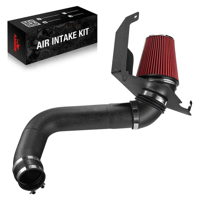
2004.5–2005 6.6L Duramax LLY
Admisión Flashark Silverado y Sierra HD LLY
Una admisión tipo escudo térmico para camiones Chevy Silverado y GMC Sierra 2500HD/3500 compatibles equipados con el 6.6L Duramax LLY.
$114.23
Comprobar compatibilidad LLYNo se publicó un precio de comparación verificado cuando se consultó. Confirme el precio actual antes de la compra.
Instalación de admisión Duramax LB7 2001–2004
El LB7 utiliza un conjunto de admisión diferente al del LLY posterior. Verifique el acoplador del lado del turbo, la abertura del sensor, la pestaña de soporte y la holgura del filtro antes de apretar el tubo.
El kit de admisión de aire frío 6.6L LB7 para Silverado 2001-2004 está destinado a camiones Duramax HD tempranos compatibles. Verifique el año de producción y el código del motor, especialmente en un camión de 2004 cerca de la transición de LB7 a LLY.
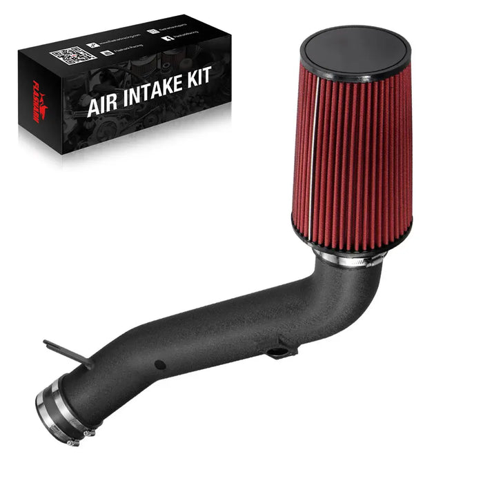
2001–2004 6.6L Duramax LB7
Admisión Flashark Silverado y Sierra HD LB7
Un tubo de admisión negro y un conjunto de filtro cónico reutilizable para camiones Chevy Silverado y GMC Sierra 2500HD/3500 compatibles equipados con el motor 6.6L Duramax LB7.
$124.43
Comprobar compatibilidad LB7No se publicó un precio de comparación verificado cuando se consultó. Confirme el precio actual antes de la compra.
La compatibilidad con Silverado y Sierra aún debe verificarse por separado
Los camiones Chevy y GMC a menudo comparten transmisiones y arquitectura de chasis, pero el embalaje delantero, el año del modelo, el estilo del sensor y la calibración del motor aún pueden afectar la compatibilidad. Los propietarios de GMC pueden comparar los kits de admisión de aire frío de GMC específicos para la aplicación en lugar de depender únicamente del título de un producto Silverado.
Errores comunes en la instalación de admisión de aire frío en Silverado
La mayoría de las instalaciones fallidas no son causadas por algún misterioso problema de la ECU. Son causadas por un detalle ordinario que se pasó por alto mientras el instalador se apresuraba a escuchar el nuevo sonido de admisión.
- MAF instalado al revés: La ECU recibe una señal de flujo de aire inexacta, lo que podría causar un ralentí irregular, vacilaciones, ajustes de combustible anormales o una luz de verificación del motor.
- Conector MAF no bloqueado: El enchufe puede parecer conectado pero soltarse después de la vibración y el movimiento del motor.
- Fuga aguas abajo del MAF: El aire entra sin ser medido, por lo que el suministro de combustible calculado ya no coincide con el flujo de aire real.
- Manguera de ventilación desconectada: Crea una fuga sustancial y puede introducir suciedad en el sistema.
- Tubo apenas insertado en un acoplador: Puede tener fugas, deslizarse o separarse con el movimiento del motor.
- Abrazadera instalada en ángulo: Aplica presión desigual y puede dejar parte del acoplador sin sellar.
- Abrazadera demasiado apretada: Puede cortar la silicona, deformar un adaptador de plástico o dañar la carcasa del MAF.
- Tornillo de la abrazadera mirando hacia una manguera o cable: Crea un punto de roce que puede no aparecer hasta varias semanas después.
- Escudo térmico apretado demasiado pronto: Desalinea el tubo de admisión y precarga los acopladores.
- Filtro tocando el escudo: Causa traqueteo y puede desgastar el material del filtro.
- Arnés del MAF estirado: El movimiento repetido del motor carga el conector y el cableado.
- Admisión de fábrica desechada: Elimina la herramienta de solución de problemas más sencilla si la camioneta presenta un problema.
Solución de problemas después de la instalación de la admisión
Ralentí irregular o calado
Trabaje a través del sistema en orden. No salte directamente a comprar un sensor.
- Confirme que el conector del MAF esté completamente bloqueado.
- Confirme que la flecha del MAF apunte hacia el motor.
- Inspeccione los terminales eléctricos en busca de pines doblados.
- Revise el sello o la junta del MAF.
- Inspeccione cada acoplador después del MAF.
- Revise las conexiones de la PCV y el respiradero.
- Asegúrese de que el filtro no esté obstruido por el embalaje o una tapa protectora.
- Lea los códigos de problema almacenados.
- Reinstale la admisión de fábrica si es necesario para aislar el problema.
Luz de Check Engine o código MAF
Una luz de verificación del motor no es una característica automática de la instalación de una toma de aire frío en un Chevy Silverado. Un sistema compatible, sellado y correctamente ensamblado no debe considerarse exitoso si activa inmediatamente un código relacionado con el MAF.
Anote el código exacto. Los códigos relacionados con el rendimiento del MAF, las condiciones de mezcla pobre, la temperatura del aire de admisión o la respuesta del acelerador apuntan a diferentes partes de la instalación. No asuma que cada código significa que el sensor MAF en sí mismo ha fallado.
Silbido o traqueteo
Se espera un mayor flujo de aire cuando se abre el acelerador. Un silbido continuo en ralentí merece una inspección.
- Presione ligeramente alrededor de los acopladores y escuche si hay algún cambio.
- Revise la junta del MAF y el asiento del tornillo.
- Inspeccione el accesorio del respiradero.
- Busque un acoplador doblado debajo del tubo.
- Verifique si un tornillo de abrazadera está tocando el escudo térmico.
- Busque marcas de contacto pulidas donde dos partes se hayan estado frotando.
¿Qué debe esperar después de la instalación?
Sea realista. Una toma de aire frío puede reducir la restricción, agudizar la nota de inducción, simplificar el servicio del filtro y admitir un paquete de flujo de aire más amplio. No sustituye la cilindrada, el árbol de levas, el flujo de la culata, los colectores, la capacidad de escape o la calibración.
Sonido y sensación del acelerador
El cambio más obvio suele ser el sonido. Bajo carga, la nota de admisión amortiguada de fábrica se vuelve más profunda y agresiva. La conducción con acelerador ligero puede permanecer bastante tranquila, mientras que una apertura más amplia del acelerador produce un rugido notable.
Algunos conductores describen el acelerador como más inmediato. Parte de eso puede provenir de la reducción de la restricción. Parte de eso proviene de escuchar el motor responder más claramente.
Expectativas de potencia
En una camioneta 5.3L sana y por lo demás estándar, un rango de planificación razonable suele ser de aproximadamente 3 a 8 caballos de fuerza adicionales en las ruedas a través de secciones útiles de la curva. Las comparaciones de picos favorables pueden mostrar alrededor de 6 a 10 caballos de fuerza. Eso no es una garantía universal y no debe aplicarse ciegamente a cada motor o admisión.
El resultado cambia con:
- Estado del motor
- Temperatura ambiente
- Eficacia del escudo térmico
- Diseño de la carcasa del MAF
- Restricción del escape
- Calibración de la ECU
- Pérdidas de transmisión y neumáticos
- Tipo de dinamómetro y procedimiento de prueba
¿La camioneta necesita un ajuste?
Un kit específico para el vehículo que conserva una geometría MAF compatible a menudo está diseñado para funcionar con la calibración de fábrica. Eso no convierte a "no se requiere ajuste" en una regla universal para cada tubo de admisión vendido en línea.
Cambiar el diámetro o la forma alrededor del MAF puede alterar la relación entre el flujo de aire real y la señal reportada a la ECU. El ajuste se vuelve más relevante cuando la admisión se combina con colectores de tubo largo, un árbol de levas, inyectores, inducción forzada u otros cambios sustanciales en el flujo de aire.
Los propietarios que aún eligen un kit pueden leer nuestra guía sobre cómo elegir una toma de aire frío para un motor 5.3 Vortec. Para otros vehículos y familias de motores, explore la gama completa de kits de toma de aire frío.
Lista de verificación final de instalación de la toma de aire frío de Silverado
- La flecha de flujo de aire del MAF apunta hacia el motor.
- El conector eléctrico del MAF está completamente bloqueado.
- El arnés del MAF tiene suficiente holgura para el movimiento del motor.
- Ningún pin del conector está doblado o empujado hacia atrás.
- Cada manguera del respiradero y de la PCV está conectada.
- Cada tubo está completamente asentado en su acoplador.
- Cada abrazadera está perpendicular al tubo.
- Los tornillos de la abrazadera permanecen accesibles para futuros servicios.
- Ningún tornillo de la abrazadera contacta una manguera, cable o panel del capó.
- El filtro está completamente asentado y seguro.
- El filtro no toca el escudo térmico o el capó.
- El escudo térmico está firmemente montado.
- El tubo de admisión no estorba el protector del ventilador y el hardware circundante.
- No quedan herramientas ni sujetadores sueltos en el compartimiento del motor.
- El motor está en ralentí de forma constante.
- No hay luces de advertencia ni mensajes de reducción de potencia.
- La admisión completa se revisará nuevamente después del primer ciclo de calor.

Aprender a instalar una toma de aire frío en una Chevy Silverado se trata principalmente de resistir la tentación de apresurarse. La dirección correcta del MAF, un arnés de cableado relajado, acopladores completamente asentados, abrazaderas accesibles y una inspección cuidadosa al primer arranque son más importantes que terminar diez minutos antes. Si se hacen bien esos detalles, la instalación debería verse limpia, seguir siendo fácil de mantener y evitar las luces de advertencia que dan mala reputación a las tomas de aire del mercado de accesorios.
¿Planeando la siguiente etapa de la construcción? Explore las mejoras de rendimiento compatibles para Chevy Silverado después de confirmar el motor, la transmisión, los requisitos de emisiones y el uso previsto de la camioneta.
Preguntas frecuentes
P1: ¿Cuánto tiempo se tarda en instalar una toma de aire frío en una Chevy Silverado?
R1: Una instalación completa atornillada suele tardar entre 45 y 90 minutos. Un GMT800 limpio y familiar puede llevar menos tiempo, mientras que los conectores frágiles, el hardware faltante, la corrosión o un diseño de escudo térmico desconocido pueden alargar el trabajo.
P2: ¿Puedo instalar una toma de aire frío en mi Silverado yo mismo?
R2: Sí. La mayoría de los kits específicos para vehículos se pueden instalar con herramientas manuales básicas por un propietario que se sienta cómodo quitando abrazaderas, desconectando sensores y verificando si hay fugas de aire. Deténgase y busque ayuda si el conector del MAF está dañado, el kit no se alinea con los puntos de montaje de fábrica o el motor funciona mal después de la instalación.
P3: ¿Debo desconectar la batería antes de instalar la toma de aire?
R3: Siga las instrucciones suministradas con el kit exacto. Desconectar el terminal negativo puede reducir el riesgo de un cortocircuito eléctrico al manipular los sensores, pero también puede restablecer los preajustes de la radio, la configuración del reloj y los valores aprendidos de la ECU.
P4: ¿En qué dirección debe mirar el sensor MAF de la Silverado?
R4: La flecha de flujo de aire debe apuntar desde el filtro hacia el cuerpo del acelerador o el motor. El conector eléctrico también debe colocarse donde el arnés de fábrica llegue naturalmente sin estirarse ni torcerse.
P5: ¿Qué sucede si el sensor MAF se instala al revés?
R5: Un MAF al revés puede informar el flujo de aire incorrectamente y puede causar un ralentí inestable, dudas, calado, ajustes de combustible anormales o una luz de verificación del motor. Corrija la dirección e inspeccione el conector y los sellos antes de borrar los códigos.
P6: ¿Por qué mi Silverado tiene un ralentí irregular después de la instalación de la toma de aire frío?
R6: Las causas más comunes son un conector MAF suelto, dirección del MAF invertida, un sello del MAF pellizcado, una fuga del acoplador después del MAF o una manguera de ventilación desconectada. Verifique la instalación física antes de reemplazar piezas.
P7: ¿Una toma de aire frío requiere un ajuste en una Chevy Silverado?
R7: Muchos sistemas específicos para vehículos están diseñados para funcionar con la calibración de fábrica cuando conservan una geometría MAF compatible. Es posible que se necesite un ajuste cuando las dimensiones de la carcasa del MAF cambien significativamente o cuando la toma de aire sea parte de una combinación más grande que involucre colectores, árbol de levas, inyectores o inducción forzada.
P8: ¿Qué tan apretadas deben estar las abrazaderas de la toma de aire frío?
R8: Apriete cada abrazadera hasta que el tubo no pueda girar o salirse con la mano. Deténgase antes de que la silicona se abulte severamente, la abrazadera corte el acoplador o un adaptador de plástico comience a deformarse. Utilice un valor de torsión publicado solo cuando el fabricante del kit lo proporcione.
P9: ¿Por qué es importante la dirección del tornillo de la abrazadera?
R9: Un tornillo de abrazadera accesible facilita mucho la inspección del primer ciclo de calor y el futuro servicio del filtro. El posicionamiento correcto también mantiene la carcasa del tornillo alejada del cableado, las mangueras de refrigerante, el capó y el escudo térmico.
P10: ¿Debo limpiar el sensor MAF durante la instalación?
R10: Límpielo solo si la inspección o el diagnóstico indican contaminación. Utilice un limpiador hecho específicamente para sensores MAF, no toque el elemento sensor y déjelo secar completamente antes de reinstalarlo.
P11: ¿Puedo conducir inmediatamente después de instalar la toma de aire?
R11: Puede comenzar una prueba de carretera corta después de confirmar un ralentí estable, conexiones seguras y que no haya luces de advertencia. No continúe conduciendo si la camioneta se detiene, acelera bruscamente, entra en modo de potencia reducida o establece un código relacionado con el MAF de inmediato.
P12: ¿Cuándo debo volver a revisar las abrazaderas de la toma de aire?
R12: Inspeccione las abrazaderas después del primer ciclo de calor completo y nuevamente después de varias conducciones normales. Los acopladores de silicona pueden asentarse y el movimiento del motor puede revelar un problema de holgura o alineación que no era obvio durante la instalación.
P13: ¿Cuánta potencia puede agregar una toma de aire frío a una Silverado 5.3L?
R13: Una camioneta de serie en buen estado puede mostrar aproximadamente entre 3 y 8 caballos de fuerza adicionales en las ruedas en partes útiles de la curva, mientras que las comparaciones de picos favorables pueden alcanzar alrededor de 6 a 10 caballos de fuerza. Los resultados dependen del diseño de la toma, el estado del motor, la temperatura, la calibración y el método de prueba.
P14: ¿Una toma de aire frío mejorará el rendimiento de la gasolina de la Silverado?
R14: Puede reducir la restricción de admisión en algunas condiciones, pero no se debe asumir una ganancia confiable en el ahorro de combustible. El tamaño de los neumáticos, la carga, el tráfico, el clima, el terreno y el uso del acelerador pueden superar fácilmente un pequeño cambio en el flujo de aire.
P15: ¿Es legal una toma de aire frío en California?
R15: La legalidad depende del producto exacto, el vehículo, el motor, el año del modelo y las normas de emisiones actuales. Verifique si el kit específico tiene una Orden Ejecutiva válida de la Junta de Recursos del Aire de California para su aplicación antes de comprarlo o instalarlo.
P16: ¿La lluvia o el agua pueden dañar una toma de aire frío de Silverado?
R16: Un filtro montado alto en el compartimiento del motor detrás de un escudo térmico generalmente está menos expuesto que una toma de aire del guardabarros montada en la parte baja, pero aún debe protegerse de lavados directos a alta presión y aguas profundas. Inspeccione el filtro si la camioneta ha sido conducida a través de lluvia intensa, inundaciones, barro o agua estancada.
P17: ¿Puedo reutilizar la toma de aire de fábrica si tengo un problema?
R17: Sí, siempre que la caja de aire, el tubo, las abrazaderas, los sellos y el hardware de fábrica se hayan guardado. Reinstalar el sistema de serie es un paso de diagnóstico útil porque ayuda a separar un problema de instalación de la toma de aire de un problema de motor o sensor no relacionado.
P18: ¿Un sonido de admisión más fuerte significa que la camioneta está produciendo más potencia?
R18: No necesariamente. Un filtro de cono abierto y un tubo más liso eliminan gran parte de la amortiguación de sonido de fábrica, por lo que el motor puede sonar dramáticamente más potente incluso cuando el aumento de potencia medido es modesto. Utilice pruebas de dinamómetro o aceleración repetibles en lugar de solo el sonido.

Steven Chen
Especialista en Rendimiento Automotriz | Sistemas de Motor y Escape
Steven se enfoca en el rendimiento práctico del motor, el ajuste del escape y las rutas de actualización del mundo real para vehículos clásicos y modernos para entusiastas. Revisa aplicaciones de bloque pequeño Ford, LS, camiones y calle/pista con un objetivo en mente: ayudar a los constructores a elegir piezas que realmente funcionen juntas. Su filosofía: "Una buena potencia comienza con la combinación correcta, no con la pieza más grande."