The 2012 Infiniti G37 uses a 3.7L VQ37VHR V6 with a dual-intake layout, so this job is different from installing a single-pipe intake on a typical four-cylinder or single-throttle-body engine. You are working with two intake paths, two throttle bodies, and two mass-airflow sensors. That makes MAF orientation, sealing, and left-to-right routing especially important.
A cold air intake installation on a G37 can still be a reasonable driveway project for someone comfortable with basic hand tools. The part that matters is not how quickly the factory airboxes come out. It is whether both intake paths go back together without leaks, wiring tension, incorrect sensor placement, or contact with surrounding components.
Quick Answer
- The 2012 G37 3.7L VQ37VHR uses a dual-intake system, so treat the left and right intake paths as separate assemblies.
- Both factory MAF sensors must remain correctly oriented, sealed, and electrically connected when the replacement intake is designed to reuse them.
- Do not fully tighten every clamp as soon as a tube fits. Align the complete system first, then tighten it without putting the tubes or couplers under tension.
- Installation difficulty depends heavily on intake design. A heat-shielded system that keeps the filters high in the engine bay is a different job from a long-tube layout that routes filters toward the front bumper or lower fender area.
- A rough idle, warning light, hissing sound, loose tube, or wiring contact after installation deserves inspection before normal driving.
- Horsepower, fuel economy, Tune requirements, and warning-light behavior depend on the intake design, MAF geometry, ECU calibration, vehicle condition, and supporting modifications. Do not treat any of them as a fixed result.
Why the 2012 Infiniti G37 Intake Layout Matters
The G37's VQ37VHR is a naturally aspirated 3.7L V6 with a symmetric dual-intake arrangement. Each side of the engine has its own airflow path feeding one of the two throttle bodies. That basic architecture needs to stay in mind throughout the installation.
This is where a generic cold air intake tutorial can get you into trouble. Instructions written around one airbox, one intake tube, and one MAF sensor do not describe the G37 correctly. On this platform, a loose connection or incorrectly installed sensor on either side can affect how the engine runs.

A dual-tube intake layout keeps separate airflow paths for the VQ37VHR's two throttle bodies.
A replacement system may use smoother tubes, open cone filters, heat shields, longer piping, or a combination of those features. The name on the box matters less than the actual routing. Two products both advertised as a "G37 cold air intake" can require very different installation work.
Heat-Shielded Intake vs. Long-Tube Cold Air Intake
Owners often use cold air intake as a broad shopping term. In practice, there are several layouts.
| Layout | Filter Position | Installation Considerations | What to Check |
|---|---|---|---|
| Heat-shielded upper-engine-bay intake | Filters remain relatively high in the engine compartment | Usually focuses on airbox removal, tube alignment, MAF transfer, heat-shield placement, and coupler sealing | Shield clearance, filter clearance, MAF orientation, tube-to-throttle-body alignment |
| Long-tube cold air intake | Filters are routed farther forward or lower in the chassis | May require additional access around the bumper, splash shields, wheel-liner area, or radiator support depending on the design | Lower-pipe clearance, water exposure, body interference, brackets, wiring, and filter access |
A longer pipe is not automatically better, and a filter sitting higher in the engine bay is not automatically wrong. Intake temperature, pressure drop, MAF behavior, routing, heat shielding, and the rest of the vehicle all matter. Choose the layout that matches the car and the way it is used.
Key Components of a G37 Cold Air Intake System
The original article described the basic pieces correctly, but the G37 needs one important addition: think in pairs.
- Intake tubes: The VQ37VHR uses two intake paths. A dual-intake system should preserve an appropriate path to each throttle body.
- Air filters: Aftermarket systems may use reusable cone filters instead of the factory enclosed panel-filter arrangement. Filter type and maintenance procedure depend on the selected system.
- MAF sensor provisions: A system designed to retain the factory airflow measurement must provide the correct mounting arrangement for both MAF sensors.
- Heat shields: Some systems position shields between open filters and hotter areas of the engine compartment. Their effectiveness depends on placement, sealing around the filter area, and the vehicle's airflow while moving.
- Couplers and clamps: These connect the tubes to the throttle-body side and to one another where applicable. A clamp can look tight while a coupler underneath it is still crooked or only partly seated.
- Brackets and mounting points: Intake tubes should not be left hanging from silicone couplers alone when the system provides structural support.
Technician's Note
Do not treat the MAF sensor as just another connector to unplug and forget. Its relationship to the airflow matters. Keep each sensor clean, preserve the correct direction, make sure its seal sits flat, and do not force the sensor into a housing that does not match.
Preparation Before Installing a Cold Air Intake on the 2012 G37
Have the intake laid out on a clean surface before removing anything from the car. Compare the left and right sides, locate the MAF mounting points, identify the filter ends, and find every bracket, coupler, and connection required for the selected configuration.
Tools and Safety Equipment
Exact fastener sizes depend on the intake and the vehicle configuration, but the job generally calls for basic hand tools rather than specialty fabrication equipment.
- Ratchet and appropriate sockets
- Screwdrivers or nut drivers for applicable clamps and fasteners
- Pliers for clips or hose clamps when required
- Trim-clip tools if surrounding panels must be moved
- Safety glasses and gloves
- A clean tray or magnetic dish for factory hardware
- A suitable light for inspecting lower connections and wiring
Work with the engine cool and the vehicle on stable ground. If the intake design requires access from underneath, support the vehicle correctly with equipment intended for that purpose. Never work under a vehicle supported only by a jack.
Before Removing the Factory Intake
- Take a clear photo of both factory intake paths before disassembly.
- Note the orientation of both MAF sensors and their electrical connectors.
- Identify every hose or wiring retainer attached to the factory intake assemblies.
- Check the replacement system against the vehicle's year, engine, body style, and drivetrain configuration.
- If the installation procedure calls for battery disconnection, switch the ignition fully off before disconnecting the negative terminal.
That first photo is worth taking. A connector that seemed obvious at the beginning of the job becomes much less obvious after both airboxes are sitting on the floor.
Step-by-Step Guide to Installing a Cold Air Intake on the 2012 G37
The sequence below applies to a dual-intake installation that replaces the factory intake tracts while retaining the G37's two MAF sensors. Bracket locations, panel removal, hose routing, and filter position can vary between intake designs, so use the instructions supplied for the selected system when they specify a different order.
Step 1: Remove the Factory Intake Assemblies
Start by loosening the intake connections at both throttle-body sides. Disconnect the two MAF electrical connectors carefully, releasing the locking tabs rather than pulling on the wires.
Remove or release any hoses, clips, resonator sections, brackets, or airbox fasteners that prevent the factory intake assemblies from coming out. Work one side at a time if that makes it easier to keep track of the routing.
Do not yank an airbox because it feels stuck. Look underneath it first. A hidden bracket, locating grommet, electrical retainer, or hose can still be attached.
Step 2: Transfer Both MAF Sensors Carefully
If the replacement intake reuses the original sensors, remove both MAF sensors from the factory housings and keep track of their installation direction. Avoid touching the sensing elements.
Install each sensor squarely into its new mounting location. The seal or gasket must sit evenly, and the sensor must not be twisted into place by overtightening its screws.

The airflow direction on a MAF housing runs from the filter side toward the engine. Use the factory orientation and intake instructions as your reference.
Do not rely only on which direction the electrical plug appears to face. Intake housings can rotate the connector differently while still requiring the sensing element to maintain a specific relationship to airflow.
Step 3: Pre-Position the New Intake Tubes
Install the throttle-body couplers and position the left and right intake tubes without fully tightening the clamps. At this stage, you are checking alignment, not finishing the job.
Make sure:
- The tube enters each coupler straight rather than at an angle.
- No tube is being pulled sideways by a bracket.
- The tubes do not press against belts, fans, wiring, coolant hoses, hood structure, or sharp body edges.
- Any hoses removed from the original intake can reach their intended connections without stretching or kinking.
- The MAF wiring reaches naturally and is not supporting the weight of the tube.
Take a minute before tightening that clamp. An intake assembled under tension can move after several heat cycles, and a coupler that looked centered during installation may start pulling toward one edge.
Step 4: Install the Filters and Heat Shields
If the system uses heat shields, install them in the position intended by the intake design and make sure they do not force the tubing out of alignment. Then install the filters securely on their respective intake tubes.
The filter should not rub against the hood, radiator support, body panel, wiring, or another component. On a long-tube design, also inspect the lower filter area for road-splash exposure and clearance through the full available space.
Step 5: Reconnect Hoses and Both MAF Sensors
Reconnect every hose, breather connection, wiring clip, and sensor connector that was moved during removal. Both MAF connectors should lock positively in place.
Trace each side from the filter toward the throttle body with your hand. This physical check catches a surprising number of mistakes because it forces you to inspect every joint rather than simply looking at the engine bay from above.
Step 6: Align the Complete System Before Final Tightening
Now look at both intake paths as complete assemblies. The tubes should sit naturally rather than being pulled into position by the clamps.
Once everything is aligned, tighten the connections progressively. Keep each clamp centered on solid clamping material. Do not place the edge of a worm-drive clamp directly on the end of a silicone coupler, and do not overtighten until the coupler distorts.

Seat the tube fully, square the clamp on the coupler, and preserve alignment before final tightening.
Step 7: Perform a Final Clearance Check
Before starting the engine, inspect the complete path on both sides.
- Both MAF connectors are fully locked.
- Both MAF sensors are installed in the correct direction.
- No wiring is stretched across a hot component or moving belt.
- Every coupler is evenly seated.
- Every required hose is connected.
- Filters and heat shields are secure.
- No tube is touching the body or another engine component.
- No tools, loose hardware, or packaging remain in the engine bay.
First Startup: What to Check Before Driving
Start the engine and let it settle while you stay next to the car. Do not immediately rev it hard just to hear the intake.
Listen for a steady idle and any obvious hissing. Watch for a warning light. Look at both intake tubes for movement. Make sure nothing is being pulled toward the radiator fan or vibrating against another component.
A different induction sound under throttle is expected with many open-filter systems. A repeated stall, severe hunting idle, strong hesitation, or warning light is not something to dismiss as the intake "breaking in."
Stop and Inspect
If the engine runs badly immediately after the intake installation, begin with the parts you just touched. Check both MAF connectors, sensor orientation, sensor seals, intake couplers, clamps, hoses, and any open ports before assuming a sensor or ECU has failed.
Common G37 Cold Air Intake Problems After Installation
| Symptom | What It Can Point To | First Checks |
|---|---|---|
| Rough or hunting idle | Unmetered air, incorrect MAF installation, disconnected hose, unstable airflow measurement, or another fault exposed during the job | Both MAFs, sensor seals, couplers, hoses, connectors |
| Warning light after installation | Airflow measurement or mixture problem, loose connection, leak, sensor issue, or calibration mismatch | Save the fault information first, then inspect both intake paths |
| Hissing sound at idle | Possible intake or vacuum leak | Coupler seating, clamps, hoses, sensor seals, unused ports |
| Tube rub or vibration | System installed under tension or insufficient clearance | Loosen affected joints, realign the complete tract, then retighten |
| Hesitation under load | Air leak, airflow measurement issue, calibration interaction, or an unrelated engine problem | Inspect installation, scan vehicle data, and compare behavior with the stock intake if necessary |
If the engine ran normally before the installation and immediately runs poorly afterward, start with the installation before replacing parts. For a more detailed diagnostic sequence, see our rough idle after cold air intake installation checklist.
Common Installation Mistakes to Avoid
1. Treating the G37 Like a Single-Intake Engine
There are two sides to inspect. Checking one MAF connector and one coupler is only half the job.
2. Installing a MAF Sensor Backward or With a Poor Seal
A MAF sensor can be electronically connected and still be mechanically installed incorrectly. Direction and sealing matter.
3. Tightening Everything Before the Tubes Are Aligned
This is one of the easiest ways to create a tube that rubs the body or a coupler that slowly walks off-center. Leave enough movement to align the system first.
4. Overtightening Clamps
A clamp needs enough pressure to seal and retain the joint. More pressure is not automatically better. Crushing a coupler or deforming a housing can create the problem you were trying to prevent.
5. Letting Wiring Rest Against Hot or Moving Parts
MAF wiring should follow a clean route with enough slack for engine movement without touching belts, fans, sharp brackets, or hot surfaces.
6. Assuming Every G37 Intake Fits Every G37
Year and engine are only the beginning. Sedan, Coupe, Convertible, RWD, AWD, and G37x configurations can affect the parts and routing required by a specific system. Match the exact vehicle configuration before ordering.
7. Ignoring Water Exposure
An open filter is designed to pass air. It cannot distinguish air from a large volume of water. Avoid deep standing water and do not direct a high-pressure water stream into an exposed filter area.
Does a Cold Air Intake Add Power to a 2012 G37?
An intake can change restriction, airflow path, inlet temperature, and the way air passes the MAF sensors. Those changes can influence engine response, but there is no responsible fixed horsepower number that applies to every G37 intake and every car.
The result depends on factors such as:
- Tube diameter and MAF housing geometry
- Filter restriction and filter condition
- Air temperature at the filter location
- Engine condition
- ECU calibration
- Exhaust and other supporting modifications
- Installation quality
- Ambient conditions and test method
The change most drivers can evaluate without a dyno is sound. Removing or reducing factory resonator volume and using exposed cone filters can make the VQ37VHR's induction note more obvious as throttle opening and engine speed increase.
Throttle feel may also change, but that is not the same as proving a specific horsepower increase. A before-and-after dyno test under controlled conditions is the right way to quantify power.
Will a G37 Cold Air Intake Improve Fuel Economy?
Do not buy an intake on the assumption that it will produce a guaranteed MPG increase. Fuel economy is affected by traffic, speed, throttle use, tire pressure, gearing, vehicle condition, ECU fuel correction, ambient temperature, and many other variables.
An intake can alter airflow restriction in part of the system, but that engineering relationship does not translate into a guaranteed fuel-economy result in normal driving.
Does a 2012 G37 Need a Tune After an Intake?
Tune requirements depend on the intake design and the rest of the car. Keeping the original MAF sensors does not by itself guarantee that every intake will behave identically to the factory system. MAF housing diameter, sensor depth, tube shape near the sensor, leaks, and airflow distribution can all affect the signal the ECU receives.
If the car has additional intake, exhaust, fuel, or engine modifications, the complete combination should be considered rather than looking at the intake in isolation. If an installation produces unstable fuel correction, repeated warning lights, or poor drivability, diagnose the mechanical installation first and use qualified calibration support when the hardware combination requires it.
Do not use a Tune to hide a loose coupler or backward sensor.
Choosing an Intake for a 2012 Infiniti G37
Start with the vehicle, not the pipe finish. Confirm the year, 3.7L VQ37VHR engine, body style, drivetrain, MAF layout, and the exact configuration listed for the intake.
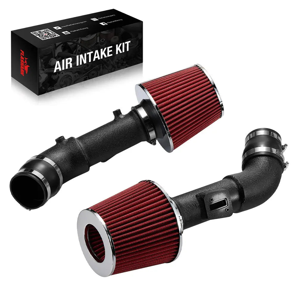
For owners comparing Flashark options, the Flashark Dual Cold Air Intake Kit, SKU FLIS08751 is listed for selected 2008–2013 Infiniti G37 3.7L VQ37VHR applications. The intake configuration uses two aluminum tubes, two cone filters, two heat shields, and provisions to retain both factory MAF sensors.
The listed tube diameter for that configuration is 2.75 inches / 70 mm. Body style and drivetrain still need to match the selected vehicle configuration, particularly when comparing RWD and G37x AWD applications.
If you are comparing several Infiniti platforms or intake layouts, browse the Infiniti cold air intake collection. For a wider range of vehicle applications, the main cold air intake collection covers additional makes and engines.
Post-Installation Inspection After the First Drive
Once the engine runs normally and the initial stationary checks pass, take a short drive rather than immediately committing to a long trip.
After the system cools again, inspect:
- Both filter connections
- Both throttle-body-side couplers
- MAF connectors and wiring
- Any breather or vacuum connections disturbed during installation
- Heat-shield and bracket hardware
- Fresh rub marks on tubes, couplers, shields, or nearby bodywork
- Clamp position after the first heat cycle
A clean installation should remain mechanically relaxed. If one side keeps shifting every time you loosen a clamp, find out what is pulling it out of position instead of simply tightening it harder.
Is a Cold Air Intake Worth Installing on a 2012 Infiniti G37?
It can make sense when the goal is a more audible induction note, a different intake layout, reusable filters, or a matched part of a broader naturally aspirated VQ37VHR setup. It is also a modification that lets a capable owner work on the car without opening the engine itself.
But the intake should be chosen for the actual G37 configuration, not because a listing promises a dramatic number. Fitment, MAF behavior, sealing, heat management, filter placement, and installation quality matter more than a marketing claim.
Get those details right and the job is straightforward in principle: preserve the VQ37VHR's dual-intake logic, keep both MAF sensors happy, eliminate unmetered-air leaks, and make sure the hardware sits naturally in the engine bay.
Frequently Asked Questions
Q1: Can I install a cold air intake on a 2012 Infiniti G37 myself?
A1: A capable DIY owner who is comfortable with basic hand tools and MAF-sensor handling can install many G37 intake systems. Difficulty increases when the design routes filters lower in the chassis or requires additional body-panel access. Professional installation is a sensible choice if sensor transfer, fitment, or vehicle support procedures are unfamiliar.
Q2: Why does the 2012 G37 use two intake tubes?
A2: The 3.7L VQ37VHR uses a dual-intake arrangement with two throttle bodies. A dual-intake system maintains separate airflow paths to the two sides of the engine rather than combining everything into one tube.
Q3: Do both G37 MAF sensors need to be transferred to the new intake?
A3: If the selected intake is designed to retain the factory MAF system, both original sensors must be installed in their intended housings, correctly oriented, sealed, and reconnected. Follow the instructions for the exact intake rather than assuming every MAF housing is interchangeable.
Q4: Which direction should the MAF sensors face?
A4: The sensing arrangement must face the airflow direction intended by the vehicle and intake design, from the filter side toward the engine. Use the original factory orientation and the intake instructions as references rather than relying only on the position of the electrical connector.
Q5: Does a 2012 Infiniti G37 need a Tune after installing a cold air intake?
A5: Tune requirements vary with intake design, MAF housing geometry, ECU calibration, and supporting modifications. Retaining the factory MAF sensors does not make every intake combination identical. Diagnose leaks and sensor-installation problems before treating calibration as the cause of poor drivability.
Q6: Can a cold air intake cause a Check Engine Light or rough idle on a G37?
A6: It can contribute to a warning light or rough idle when a MAF sensor is installed incorrectly, a connector is loose, a seal leaks, a hose is left disconnected, or unmetered air enters the intake. A warning light should be diagnosed rather than treated as a normal part of the modification.
Q7: How much horsepower does a cold air intake add to a 2012 G37?
A7: There is no single horsepower number that applies to every G37 intake. Results depend on intake geometry, filter design, MAF behavior, ECU calibration, engine condition, supporting modifications, ambient conditions, and installation quality. A controlled before-and-after dyno test is required to quantify the result.
Q8: Will a G37 cold air intake improve fuel economy?
A8: Fuel economy should not be expected to improve by a fixed amount. Driving style, traffic, speed, vehicle condition, ECU correction, tire pressure, temperature, and other factors can have a larger effect on MPG than the intake alone.
Q9: Does the same intake fit G37 Sedan, Coupe, Convertible, RWD, and G37x AWD models?
A9: Do not assume that a shared engine automatically guarantees identical fitment. Body style and drivetrain can affect brackets, pipe routing, clearances, and surrounding components. Match the exact year, body style, engine, and drivetrain to the selected intake before ordering.
Q10: What is the difference between a heat-shielded intake and a long-tube cold air intake on a G37?
A10: A heat-shielded system generally keeps the filters higher in the engine compartment and uses shielding to reduce direct heat exposure. A long-tube system routes the filters farther forward or lower toward cooler outside airflow. The longer layout can require more installation access and needs additional attention to water exposure and chassis clearance.
Q11: Is it safe to drive a G37 cold air intake in the rain?
A11: Normal wet-weather driving is different from submerging an exposed filter. Avoid deep standing water, flooding, and direct high-pressure spraying around the filter area. Lower-mounted filters deserve extra caution because water ingestion can damage an engine.
Q12: What should I check before the first drive after installing the intake?
A12: Check both MAF connectors, sensor orientation, every coupler and clamp, hose connections, filter security, heat-shield clearance, wiring clearance, and tube-to-body contact. Start the engine first and confirm that it idles normally without a warning light or obvious air leak.
Q13: Should I disconnect the battery before installing a G37 intake?
A13: Follow the vehicle and intake instructions for the selected installation. If battery disconnection is called for, switch the ignition fully off before removing the negative terminal. Be aware that disconnecting power can affect stored settings or require vehicle-specific relearn procedures afterward.

Steven Chen
Automotive Performance Specialist | Engine & Exhaust Systems
Steven focuses on practical engine performance, exhaust fitment, and real-world upgrade paths for classic and modern enthusiast vehicles. He reviews small-block Ford, LS, truck, and street/strip applications with one goal in mind: helping builders choose parts that actually work together. His philosophy: "Good power starts with the right combination, not the biggest part."