


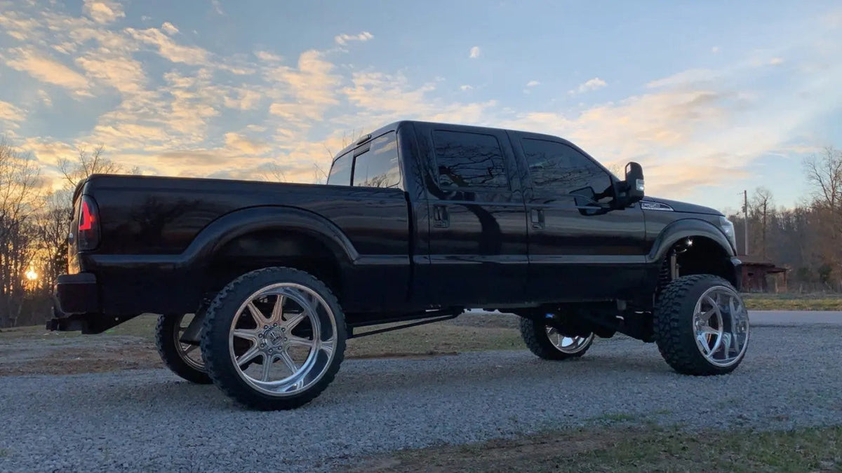
This guide covers the physical removal and block-off process described for a 2015-2016 Ford Super Duty truck with the 6.7L Powerstroke diesel engine. Before ordering parts or beginning work, confirm your vehicle year, engine, drivetrain, selected product configuration, and local road-use requirements.
- This is an advanced repair procedure involving the intake system, coolant lines, wiring connectors, and EGR hardware.
- Allow the engine to cool completely, disconnect both batteries, and collect coolant in a clean drain pan before opening the cooling system.
- Vehicle configuration, emissions equipment, wiring condition, exhaust leaks, and calibration can affect warning-light behavior and final operating results.
- Review local emissions and road-use requirements before modifying emissions-related equipment.
- Match the part to the vehicle before installation, and review the selected product configuration and package contents before disassembly.
The Bottom Line: What to Expect from This Install
The EGR system routes a controlled amount of exhaust gas through the intake tract under certain operating conditions. On an older truck with EGR-related leaks, deposits, damaged hoses, or cooling-system concerns, inspecting the complete system can help identify the source of the problem. Removing or changing related hardware affects a connected system that includes intake plumbing, cooling components, sensors, wiring, emissions equipment, and calibration.
Take a minute before starting the job. The physical work is only one part of the decision. Confirm the vehicle configuration, inspect the selected hardware, and understand the local requirements that apply to emissions-related modifications.
Job Specifications & Required Tools
- Difficulty level: Advanced mechanical work
- Tools used in this procedure: metric socket set, 8mm, 10mm, and 13mm sockets or wrenches, Torx bits, extensions, wrenches, pliers, a flathead screwdriver, a coolant drain pan, and penetrating oil.
- Additional preparation: eye protection, clean shop towels, containers for removed hardware, and a safe way to support and organize disconnected harnesses and hoses.
Never work on a hot vehicle. Allow the engine to cool fully before opening the cooling system or handling exhaust-side hardware. Use eye protection, keep coolant away from children and animals, and inspect every electrical connector and hose before restarting the engine.
On used trucks, exhaust fasteners can be difficult to remove. Apply penetrating oil to accessible fasteners before disassembly and avoid forcing hardware that is binding. A damaged fastener, connector, hose, or sealing surface can turn a straightforward repair into a larger job.
Phase 1: Preparation & Teardown
- Disconnect both batteries.
- Drain coolant from the hot and cold side of the radiator into a clean drain pan.

- Unplug the MAF sensor located on the intake. Release the red tab before removing the connector.

- Using an 8mm wrench, remove the two bolts holding the intake box and reservoir chamber in place.
- Loosen the two clamps on the intake coupling that attaches the intake box to the manifold.
- Pull up on the intake box to remove it from the rubber mounts.
- Pull the three coolant lines from the clips on the remaining intake tube, then remove the remaining intake tube.
- Disconnect the clips and brackets retaining the two larger coolant lines going to the EGR cooler. Remove the lines carefully.


- Remove the two hose clamps on the small coolant-line T. Disconnect the lines and install the supplied straight barbed fitting only if it matches the selected kit instructions.
- Install the coolant line from the degas tank to the disconnected radiator port only as directed by the selected hardware instructions.
Plastic fittings around the degas tank may become brittle after repeated heat cycles. Support the fitting while removing a hose, and stop if the plastic begins to flex excessively.
- Disconnect the quick-connect coolant line from the driver side of the EGR cooler.
- Disconnect the EGR temperature-sensor connector. Secure the vehicle-side connector and harness away from hot or moving components.
- Unplug the PCM harness from the passenger-side firewall and secure it out of the work area.
Where Are the EGR Cooler and Temperature-Sensor Connections?
In this procedure, the EGR cooler, related coolant lines, and temperature-sensor connection are accessed after the intake components are removed. Connector routing can vary with vehicle configuration and previous repairs, so trace each harness before disconnecting it. Do not pull on wires; release locking tabs and support the connector body.
Phase 2: EGR Cooler & Pipe Removal
- Unplug the harness on top of the EGR cooler. The harness in this procedure contains an orange connector with a yellow locking tab, a grey connector, and a black connector with a metal clip. Retain clips for reassembly.
- Disconnect the vacuum line on top of the EGR system. Remove the hard plastic line from the rubber 90-degree fitting and cap the line only as directed by the selected hardware instructions.
- Unplug the butterfly-valve connector next to the fan shroud.
- Remove the two bolts securing the wiring harness to the EGR cooler.
- Remove the two clips on the passenger-side heat shield below the EGR cooler.
The EGR pipe fasteners are a common stopping point. Apply penetrating oil, use the correct tool engagement, and avoid sudden force. If a fastener begins to bind or twist, reassess before continuing.
- Remove the short EGR pipe secured by four bolts. Keep hardware and gaskets organized for inspection.
- Remove the longer EGR pipe secured by five bolts: two bolts at each flange and one at the support bracket. Keep the hardware organized.
- Remove the seven bolts holding the EGR cooler in place.
- Remove the nut securing the hard pressure line at the rear of the EGR cooler near the firewall.
- Move the EGR system upward and toward the front of the truck as clearance allows. Remove any remaining clips or harnesses attached to the cooler before lifting it out.

Phase 3: Block-Off Plates & Reassembly
- Install the exhaust block-off plate using the appropriate hardware and sealing components for the selected configuration.
- Install the coolant block-off plate with the applicable supplied hardware.
- Reconnect the PCM harness and make sure connectors are fully seated.
- Reconnect the quick-connect coolant line and confirm it is fully locked in place.
- Secure EGR-related wires and vacuum lines away from heat, sharp edges, and moving components.
- Install the intake block-off plate with its O-ring and the applicable hardware. Do not reuse a gasket where the selected hardware instructions specify an O-ring seal instead.

- Install the supplied mounting bracket and hardware to support the hard pressure line, following the selected kit instructions.
- Reinstall the intake components, including the intake box, couplings, and MAF sensor.
- Refill coolant according to the vehicle manufacturer's service information. Run a careful leak inspection after the engine reaches operating temperature, then recheck coolant level after the engine cools.
Phase 4: Coolant Re-Route Hose Installation
- Install the new bracket supplied with the selected configuration.
- Install the new coolant re-route hose as directed by the selected hardware instructions.
- Reconnect the 90-degree end of the coolant hose at the firewall and inspect the connection before filling the system.
Before Reassembly: A Practical Decision Check
| Area to Check | Why It Matters | What to Confirm |
|---|---|---|
| Vehicle configuration | Similar-looking 6.7L Powerstroke components are not automatically interchangeable. | Year, engine, drivetrain, and product configuration. |
| Cooling system | Incorrect hose routing or an unsecured connection can cause leaks or air pockets. | Hose seating, clamps, quick-connect locks, coolant level, and leak inspection. |
| Electrical connectors | Wiring condition and connector placement can affect vehicle operation and warning-light behavior. | Locks engaged, harnesses supported, and wiring kept away from heat and moving parts. |
| Sealing surfaces | Damaged gaskets, O-rings, or surfaces can lead to leaks. | Clean mating surfaces and the correct sealing method for the installed hardware. |
Choosing the Correct EGR Delete Kit Configuration
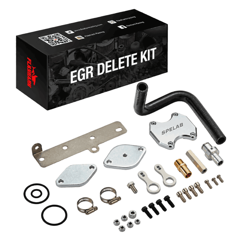
Two similar-looking kits may not use the same routing, plates, fittings, or installation sequence. Confirm the vehicle year, engine, and selected configuration before ordering. If you are comparing options, review the available EGR delete kit configurations and contact customer support if you need help identifying the correct configuration.
Do not use a generic fitment statement as a substitute for checking the selected product. Product configuration and package contents should match the vehicle before installation begins.
Frequently Asked Questions
Q1. Do I need to inspect the wiring and connectors after working around the EGR system?
A1. Yes. Inspect every connector, locking tab, and harness routing point before reassembly. Keep wiring away from exhaust-side heat, sharp edges, and moving components.
Q2. Will this guide fit a 2017 Ford F-250 6.7L?
A2. This procedure is written for the 2015-2016 6.7L Powerstroke layout. Confirm the exact vehicle year, engine, drivetrain, and product configuration before using any installation instructions on another model year.
Q3. What should I do before opening the cooling system?
A3. Let the engine cool completely, disconnect the batteries, prepare a clean drain pan, and follow the vehicle manufacturer's coolant-service guidance. Hot coolant can cause serious burns.
Q4. Why should I use penetrating oil on EGR pipe fasteners?
A4. Heat cycles and corrosion can make exhaust-side fasteners difficult to remove. Penetrating oil may help reduce the chance of damaging hardware, but it does not guarantee easy removal.
Q5. What should I inspect before installing a block-off plate?
A5. Inspect the mating surface, sealing method, hardware condition, and alignment. Use the sealing components and installation sequence specified for the selected hardware.
Q6. Where is the EGR temperature-sensor connection in this procedure?
A6. The connector is accessed after the intake components are removed. Trace the harness before disconnecting it, release the locking tab, and secure the vehicle-side connector away from heat and moving parts.
Q7. Can a coolant leak appear after the first heat cycle?
A7. It can. After reassembly, inspect hose connections, quick-connect locks, clamps, and sealing surfaces. Recheck coolant level only after the engine has cooled safely.
Q8. What can affect warning-light behavior after changes to related hardware?
A8. Tune requirements vary by vehicle and installed hardware. Sensor location, exhaust leaks, wiring condition, emissions equipment, and calibration can affect warning-light behavior.
Q9. Should I expect a specific power or fuel-economy result?
A9. No fixed power, temperature, or fuel-economy outcome should be assumed. Results can vary with engine condition, vehicle configuration, load, maintenance, fuel, calibration, and the rest of the intake and exhaust system.
Q10. What should I do if a fastener breaks or a connector is damaged?
A10. Stop before reassembly and address the damaged component correctly. A broken exhaust fastener, damaged connector, or compromised sealing surface can create a larger repair if it is ignored.

Steven Chen
Automotive Performance Specialist | Engine & Exhaust Systems
Steven focuses on practical engine performance, exhaust fitment, and real-world upgrade paths for classic and modern enthusiast vehicles. He reviews small-block Ford, LS, truck, and street/strip applications with one goal in mind: helping builders choose parts that actually work together. His philosophy: "Good power starts with the right combination, not the biggest part."







1 comment
Eric Scott
Do I need to get with a hose or not?